Saturday, January 25, 2014

Instantaneous and Average Power


__________________________________________________


I've learned that in solving power, there are many different ways and different formula but comes up with the same answer. I also learned that resistor is the resistive load which also absorbs power from the source. This means that most loads in our home are resistive because we are paying bills for the power we consumed.


I've learned that in AC source capacitors are able to store Power and releases power. They are not like resistive loads that absorb power and dissipate power in the form of heat. 

Saturday, January 11, 2014

Thevenin's and Norton Theorem


Thevenin's Theorem- states that any network of voltage sources and resistors can be reduced to a single voltage source and a single resistor which are in SERIES with each other.


Example problem;


             In the circuit above we are required to obtain the thevenin's circuit equivalent.

thevenin's circuit equivalent


                           To achieve this goal, on the circuit given above we must acquire Vth and Zth. To do this, in getting Zth we first kill all sources present in the circuit. We have


So let's apply the series-parallel combination.

* -  means series
//  means parallel

j2 Ω * 6 Ω

Z1 = 6 + j2  Ω


Z1// -j4

Z2 = (6+j2)(-j4)   /    (6+j2)+(-j4)

Z2 = 12/5   -  j16/5   Ω

Z2 * 10 Ω

Zth = 62/5 - j16/5 Ω


 next is to solve for Vth. let's use again our 1st circuit.


                 In solving Vth we can apply any analysis that is fit to the circuit. We will use KVL.

75
 20 = 6 I + j2 I + (-j4) I

75
 20 = I (6  + j2  + (-j4))

I =  11.86
 38.43 A


Vth= I x Z (capacitor)

Vth =  11.86
 38.43 x  (-j4)

Vth = 47.43
 -51.565 


What happen to 10  Ω resistor?


Our circuit on the right side is open. one terminal of our resistor is hanged. Therefore there is no current present across this resistor.


our thevenin equivalent circuit is :


                  I've learned that in solving circuit using thevenin's theorem in AC circuit it has the same application as we solve the dc circuits.The difference is the application of complex numbers. 


Friday, January 10, 2014

Source Transformation

Source Transformation

In source transformation we have to combine the impedances or simply the circuit. But remember that we must leave the branch which is the required parameter is present on it.

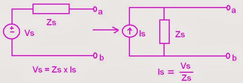
Also in source transformation we will transform the voltage source in series with impedance to a current source in parallel with impedance or vise-versa. The transformation of the source with impedance will only use the ohm's Law
Vs = Zs x Is and Is = Vs / Zs.

Illustration:


Example:


                               Vx is our unknown in the given circuit. We have to simplify this circuit to obtain Vx.

* means series
3Ω *  j4 Ω

Z1 =  3 + j4   Ω

4 Ω * -j13 Ω

Z2 = 4 + -j13 Ω


As we can see from the circuit, It has a voltage source with series resistor. We will transform it into a current source with a resistor as what illustration above shows. Using ohm's Law we have;


I = (20-90)   /   5   =  -j4 A


5 Ω // (3+ j4 Ω)

Z3 = (3+ j4) (5) /   (3+ j4) + (5)
Z3 = 2.5 + j1.25 Ω


V =   (-j4) x (2.5 + j1.25)
V =  5 - j10 V


   (2.5 + j1.25 Ω) *  (4 + -j13 Ω)

  Z4 =  (2.5 + j1.25) + (4 + -j13) 

  Z4 = 6.5 - j11.75 Ω


By this time, we will apply voltage division.

Vx = ( Zx ) (Vs)    /    (Zx) + (Z)

Vx = ( 10 ) (5 - j10)  /   ( 10 )  (6.5 - j11.75)

Vx =  5. 519  -27.98 V


I've learned that in solving unknown in Ac circuit, we can also use source transformation. For me this is much easier to use than to the other in simplifying the circuit because it lessen your time making solutions. It gives you many illustrations how the circuit changes while solving the problem. Ohm's Law is the most formula we used in here so it is quiet easy. Source transformation can be use for checking your circuit if you are confused.


Saturday, December 14, 2013

Superposition Theorem


               In our previous discussion we learned that the forced steady-state response of circuits to sinusoidal inputs can be obtain by using phasor where this phasor is in complex form. In this section we will discuss about in the superposition theorem in the form of phasors in knowing current and voltages. 

               The principle of superposition states that the response (a desired current or voltage) in a linear circuit having more than one independent source can be obtained by adding the responses caused by the separate independent sources acting alone.

              The superposition theorem gives a method for finding the currents in the circuit which then enables all the voltage drops to be calculated. The procedure is described below:


-Redraw the circuit for each e.m.f. in turn shorting out the other e.m.f
-Calculate the currents that would flow due to each e.m.f. acting alone
-Finally add the branch currents from each of the circuits (taking into account their direction*) to find the branch currents for the original circuit
-Use these currents to find the voltage drops in the original circuit


Example problem:


             Using super position we have to kill sources across the circuit and leave one voltage source. We have two sources. This means that we have two circuits. We have to solve each of its current at the same branch.

Killing the current source

 Remember that we should leave voltage source, current must be set to zero and the path leaved open.


In the circuit we can now perform the series-parallel to make it simpler.
8  Ω * j10  Ω          (* means series)

Z1 = 8  Ω + j10  Ω

Z1 // -j2  ( below capacitor)               // means parallel

Z2 = (8 + j10 )(-j2)   /    (8 + j10 ) + (-j2)

Z2 = 1/4  -  j 9/4

Z2  *  -j2   (above capacitor)

Z3 =  (1/4  -  j 9/4)  +   -j2

Z3 =  1/4  -  j 17/4


  =tis illustration is the a branch contains a multiple of impedance came from different branches after simplifying the circuit.


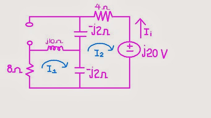
This circuit we are looking for current of 4Ω so we will use KVL.


(1/4  -  j 17/4) I  +  4 I  = -j20

((1/4  -  j 17/4) +  4 ) I  = -j20

I = 2.353 - j2.353

Since I =  -I1        (negative because of the opposite directions of currents)

I1 =  - 2.353 + j2.353 A
I1 =  3.33  135 A    (first current)


Killing the voltage source


                   We have to remember that, it is important to leave the branch that has the required unknown value at ease so that we can easily get its value. (I am talking about the 4 Ω resistor)

In this circuit we can use mesh analysis for better calculations.

I3 =  5 A     --------> equation 1

@ mesh 1


8 I1 + j10 I3 - j10 I3 - j2 I1 + j2 I2 = 0

Since we already have I3, substitute this equation @ mesh 1

I1 (8+j8) + j2 I2 = 50i   ---------> equation 2

@mesh 2

-j2 I2 + - j2 I1 - j2 I2 + j2 I3 + 4 I2 =0

I2 (4-4j) + j2 I1 = -j10 --------> equation 3

Using matrix,

 (8+j8)       j2         = 50i
  j2           (4-4j)     = -j10     


            Δ2 =   (8+j8)(4-4j) + (  j2 )(  j2 )

Δ =  68

We will only solve the I2 in the equation. We don't need I1.


Δ2 =   (8+j8)(-j10 )  -  (50i)(j2 )

Δ2 = 180 - j80

So,

I2= (Δ2  /  Δ)

= (180 - j80)  /   68

= 2.90 
-23.96  A   (second current) 


Our first current is  3.33  135 A and second current is 2.90  -23.96  A. To get the actual value of the required parameter we will add up the two current.

Yields,

Total current I = 3.33  135     +      2.90  -23.96

                   I = 6.116144.978 A


_____________________________________________
* Note to add the branch currents while taking into account their direction may actually require one current to be subtracted from another. If both currents are flowing in the same direction you simply add them, but if the currents are flowing in opposite directions you subtract the smaller current from the larger one. The resultant current will flow in the same direction as the larger current.


I've learned that in super position theorem can be apply to AC circuits. And its application is the same way to DC circuits. The difference is, it uses complex number in AC circuit. I learned that this theorem is very useful when the sources are in different frequencies.

I also learned that since source are in different frequencies the impedance must be solved in separate but the same circuit and contains one source (the rest must be set to zero or kill) it is because impedance depends on frequency. With this, each circuit must produce required values of the required parameter.


Friday, December 6, 2013

mesh analysis

mesh analysis

We already have a background in solving circuits using the mesh analysis. We are now ready to put things more complicated using the complex number as what we had tackled previously.

Mesh analysis
Mesh is a loop which does not contain any other loop within it.

                In solving with mesh analysis, our basis is the Kirchhoff's voltage law or (KVL). This will give us a set of equations that we will solve to find the mesh currents. Once we find the mesh currents we can use them to calculate any other currents or voltages. Remember that in using KVL in every mesh we have to make all resistors to be positive. And for the voltages that are passed by the loops, there are two signs shown, so you have to get the first sign. You may wonder why I solve that way.Iit is because I want to lessen the negative signs so that I may not be confused in distributing signs.

Remember again that we have to consider that there are some elements that contain two meshes but we don't need to explain it further for i know that you already taken circuits 1.

(See problem below to see how it works).


Example Problem:


For the circuit above our task is to get the current across the 4 Ω resistor.


Loop 1, loop 2 and loop 3 are what we called the meshes. We will follow this loop to get the equations from the circuit and to solve for the current which is Io = - I2 or I2 = -Io.

Negative because the direction of I2 is opposite to the direction of our Io.


We will start,

              @ Mesh 1
           
                  8 I1 + j10 I3 - j2 I1 + j2  I2 = 0

                  I1 (8+j8) + j2   I2 - j10 I3 = 0   ------> equation 1

             @ Mesh 2
             
                  -j2 I2 + j2 I1 - j2 I2 + j2 I1 + 4 I2 + 2090 = 0

                    I2 (j4-4) -  - j2 I1  - j2 I3  =  2090 ----------> equation 2
                 
             
              @ Mesh 3


                   I3  =  50 A            ------------->  equation 3
             
                   They have the same direction so current is positive.


              We already have I3 so we will substitute  equation 3 to  equation 1 and  equation 2 since the two equation contain I3.

          Our new equations are:

                 I1 (8+j8) + j2   I2  = j50   ------> equation 1

                  I2 (j4-4)  - j2 I1   =  j30 ----------> equation 2

Using matrix,

              (8+j8)      j2     =  j50

               - j2       (j4-4)   =  j30 

   
            Δ =  (8+j8)(j4-4) - ( - j2)( j2)

            Δ =  - 68

The required value is the Io so we have to get the I2. we will solve only I2. We don't need I1.

            Δ2 =  (8+j8)(j30 ) - ( - j2 ) (j50)

Yields,

           Δ2 =  -340 + j240

So,

              I2 =  (Δ2 / Δ)

              I2 =  ( -340 + j240)  /   (- 68)

              
              I2 =   6.12-35.22

                      
 Io =   6.12-35.22


              I've learned that In mesh analysis, from previous discussion, its basis is still the Kirchhoff's Voltage Law but the current, voltages and impedance are expressed in complex numbers and the voltage source and current source is expressed in phasor or time domain.

            As I have said from nodal analysis, in solving mesh analysis, it has the same steps in solving circuits. The only difference is it gets more complicated because there are sometimes you will confused yourself because it makes longer equation to write, additional variables and has two terms that is assigned in one element. In super mesh has the same step from previous discussion of mesh analysis we only need patience and apply the basic to more complicated problems.

Friday, November 29, 2013

nodal analysis

Nodal analysis with complex

              Nodal analysis defines as knowing the current and voltage using nodes, where nodes are set to be V1, V2, V3 …....and Vn, and find the current of each elements that are connected to the nodes. In nodal analysis we have to consider the cases that are given: Case 1: If the voltage source (dependent or independent) is connected between two non-reference nodes, the two non-reference nodes form a generalized node or super node. We apply both KCL and KVL to determine the node voltages. Case 2: if a voltage source is connected between the reference node and a non-reference node, we simply set the voltage at the non-reference node equal to the voltage of the voltage source.


The total current entering a node equals the total current leaving a node.


Example:


             On this circuit we are required to get the ix that passes through the capacitor 0.1F.
                                V= 200   ω= 4
            In this circuit we can produced two nodes (Node 1 and Node 2). Before we going to redraw our circuit we have to express our Inductor and Capacitor Impedances into complex number.
         Let Zc be the impedance of the capacitor
         Let Zh be the impedance of 1 H inductor 
         Let Zn be the impedance of 0.5 H inductor

                Zc =   1  /  jωC    =   1  /  j(4)(0.1)    

                                          =    -j2.5

                Zh =     jωL    =    j(4)(1)    

                                          =    -j4

                Zn =     jωL    =    j(4)(0.5)    

                                          =    j2


Let's redraw our circuit;


            We have already our circuit that is expressed in complex number. We can now apply nodal analysis.


                  @ node 1

           (V2 - V1)  /  j4   =     (V1 - 20
0) / 10   +     V1  /  (- j2.5)

          10 (  (V2 - V1)  /  j4   =     (V1 - 20
0) / 10   +     V1  /  (- j2.5))

Yields,

          (j1.5 + 1) V1 + j2.5 V2  = 20 ----->    Equation 1


                    @ node 2

          (V2 - V1) / j4    +    (V2/j2)   =  2ix

          ix = V1/ -j2.5

          (V2 - V1) / j4    +    (V2/j2)   =  2 (V1/ -j2.5)

          20((V2 - V1) / j4    +    (V2/j2)   =  2 (V1/ -j2.5))
          
Yields,

          j11V1 + j15V2 + 0   ------------->  Equation 2

Apply matrix;

                   (j1.5 + 1)         j2.5            =      20
                        j11             j15             =      0

Δ =         (j1.5 + 1)(j15 )   -   (  j11)( j2.5)
Δ =         5 + j15


next is to solve for Δ1


Δ1 =  20(
 j15 )  -   ( j2.5 )(0)
Δ1 =   j300


So,

            V1=  (Δ1 /  Δ)  =    j300  /  ( 5 + j15 )


Yields,

           18.97
18.43  V


                        I've learned that in nodal analysis we commonly used the 
kirchhoff's Current Law. As this Law is implemented to the circuit we first know the value of voltage since the voltages play as the variables of the equation of the given circuit. In super node, I learned that  the process in solving the circuit is just the same in solving DC circuit, but this time our voltages sources is in AC and it is expressed in time domain or phasor domain.