Monday, October 14, 2013
Basic theory and Ohm’s Law
Basic electric circuit
Current
is the flow of electrical charges.
Voltage
is referred to as potential difference or electromotive force (emf).The force that pushes electron.
through the wire.
Resistance
impedes the current.
Current that passes through the wire indicated as I, for Voltage is V and our Resistance is R. these
are the abbreviation that is used universally.
Units:
I=ampere (A)
V=voltage V
R=ohm (W),
Current
Here we have the basic electrical circuit. We have a battery serves as our power source, bulb that is
also known as our load, wire that connects to a light, a switch that use to on and off the circuit.
image
Open circuit
When the switch is open (not connected), it is in the state of open circuit and there are no electrical charges that are able to pass completely to the path of the circuit.
In an open circuit the current is zero, resistance is infinite and voltage could be anything.
Close circuit
Now, when the switch is closed, the current from the battery runs through the wire and passes through the bulb and back to the battery. This is now the time the bulb lights up.
In a colsed circuit the voltaget is zero, resistance is zero and current could be anything.
Voltage
We normally think our voltage is in the battery. Voltage is the one that pushing the electrons to the wire.
Resistance
Resistance is the one that resist the current. Our light creates resistance and as a result it has a voltage drop a cross on it. That is what causes the bulb lights up.
Ohm's Law
We already touched on the three terms voltage, current and resistance. Now it is time to discuss them further. Ohm’s Law defines as an important relationship between three very important electrical properties. Let’s take a look of some illustration to understand these three components.
The water in the tank pushes down on the water in the pipe. As the gravity is pulling on the water it makes the flow faster. That is how our voltage pushes electron.
Water flows from the pipe is our current. The greater the force that is exerted the faster the water flows.
and finally, our resistance is like the valve that we use to turn it clockwise and counter clockwise to make the water flows slowly.
Relationship
To understand the relationship of the three important components let us consider the illustration bellow.
To find Voltage we multiply I and R.
for V = I x R
As the Voltage increases the current
also increases.
To find resistance we devide V by I.
for R = V ÷ I
To find current we divide V by R
for I = V ÷ R
As the resistance increases
current decreases.
Knowing one of this formula is easy to derived to get the desired component.
_________________________________________________________________________
_________________________________________________________________________
Capacitors and Inductors
Capacitors
are components that are used to store an electrical charge and are used in timer circuits. A capacitor may be used with a resistor to produce a timer. Sometimes capacitors are used to smooth a current in a circuit as they can prevent false triggering of other components such as relays. When power is supplied to a circuit that includes a capacitor - the capacitor charges up. When power is turned off the capacitor discharges its electrical charge slowly.
are components that are used to store an electrical charge and are used in timer circuits. A capacitor may be used with a resistor to produce a timer. Sometimes capacitors are used to smooth a current in a circuit as they can prevent false triggering of other components such as relays. When power is supplied to a circuit that includes a capacitor - the capacitor charges up. When power is turned off the capacitor discharges its electrical charge slowly.
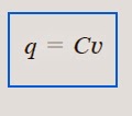
The capacitor is said to store the electric charge. The amount of charge stored, represented by q, is directly proportional to the applied voltage v so that..
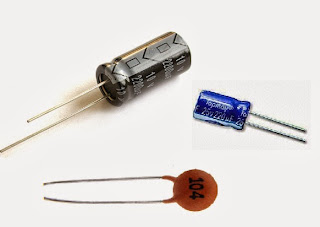
illustration below shows some types of
capacitor
Series and parallel Capacitors
series formula
parallel formula
Inductors
An inductor is a passive electronic component that storesenergy in the form of a magnetic field. In its simplest form, an inductor consistsof a wire loop or coil. The inductance is directly proportional to the number of turns in the coil. Inductance also depends on the radius of the coil and on the type of material around which the coil is wound.
series and parallel inductors
series
Inductance = L
Inductors in series are combined in exactly the same way as resistors in series.
Parallel
Inductors in series are combined in exactly the same way as resistors in parallel.
Thevenin's Theorem, Norton's Theorem and Maximum Power Transfer
Thevenin's Theorem
Thevenin's Theorem states that any network of voltage sources and resistors can be reduced to a single voltage source and a single resistor which are in SERIES with each other.
thevenin's theorem is to let you simplify the complicated circuit. So to make it, we need to what it is.
In solving thenenin's theorem we have to fine first the equivalent voltage Vth and the resistance Rth. lets solve some problem to understand it better.
Find the thevenin'n equivalent circuit shown.
we can get Rth by turning off the32-V voltage source (shorted) and the 2-A current source (opened).
Thevenin's Theorem states that any network of voltage sources and resistors can be reduced to a single voltage source and a single resistor which are in SERIES with each other.
thevenin's theorem is to let you simplify the complicated circuit. So to make it, we need to what it is.
In solving thenenin's theorem we have to fine first the equivalent voltage Vth and the resistance Rth. lets solve some problem to understand it better.
Find the thevenin'n equivalent circuit shown.
Rth= 4 // 12 + 1= 4 ohms
to find Vth let us apply the mesh analysis to the two loops..
solving for I1 we get 0.5 A
this circuit contains no dependent source. Just remember to solve this kind of circuit you get first the Rth and Rth and the remaining will follow. If you will encounter circuits that has dependent source leave it on the circuit and kill all dependent source and assume voltage source to the circuit where you are required to get.
Norton's Theorem
Norton's Theorem states that
it is possible to simplify any linear circuit, no matter how complex, to an
equivalent circuit with just a single current source and parallel resistance
connected to a load.
You will determine if what kind to theorem you are going to use, we already know what thevenin's theorem has
Let's take a look of some example:
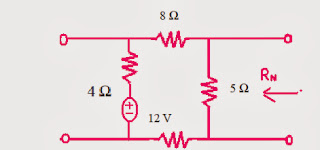
The same as thevenin's theorem, we get Rn by setting all independent source into zero.
To find Rn we will short circuit terminals a and b and ignore 5 ohms resistor because it has been shorted. applying mesh we can get.
we obtain
Maximum Power Transfer
states that to obtain maximum power from a source with a fixed internal resistance the resistance of the load must be made the same as that of the source.
Therefore we conclude that RL = Rth
To obtain maximum power transferred
superposition
superposition
The
principle of superposition states that the response
(a desired current or voltage) in a linear
circuit having more than one independent source can be obtained by adding the
responses caused by the separate independent sources acting alone.
remember that:
remember that:
sample problem
If
superposition of the controlled source is not used, two solutions must be
found. Let i = ia+ib, where ia
is the
current with the 7A source zeroed and ib is the current with the 24V source zeroed. By superposition,
we can
write
This is the
same answer obtained by using superposition of the controlled source.
Subscribe to:
Comments (Atom)


