Saturday, December 14, 2013

Superposition Theorem


               In our previous discussion we learned that the forced steady-state response of circuits to sinusoidal inputs can be obtain by using phasor where this phasor is in complex form. In this section we will discuss about in the superposition theorem in the form of phasors in knowing current and voltages. 

               The principle of superposition states that the response (a desired current or voltage) in a linear circuit having more than one independent source can be obtained by adding the responses caused by the separate independent sources acting alone.

              The superposition theorem gives a method for finding the currents in the circuit which then enables all the voltage drops to be calculated. The procedure is described below:


-Redraw the circuit for each e.m.f. in turn shorting out the other e.m.f
-Calculate the currents that would flow due to each e.m.f. acting alone
-Finally add the branch currents from each of the circuits (taking into account their direction*) to find the branch currents for the original circuit
-Use these currents to find the voltage drops in the original circuit


Example problem:


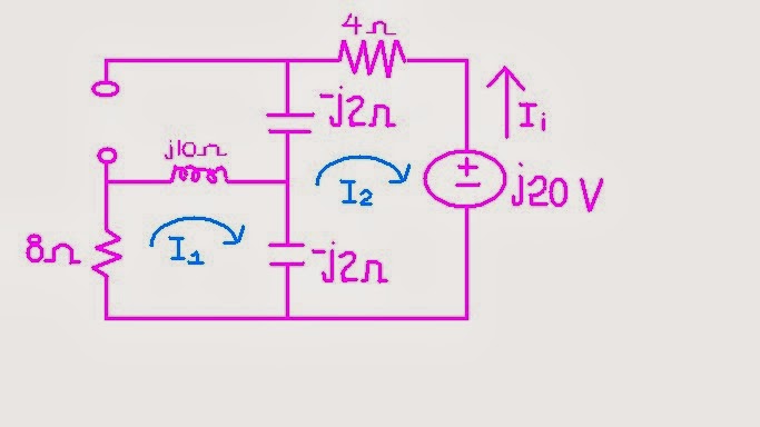
             Using super position we have to kill sources across the circuit and leave one voltage source. We have two sources. This means that we have two circuits. We have to solve each of its current at the same branch.

Killing the current source

 Remember that we should leave voltage source, current must be set to zero and the path leaved open.


In the circuit we can now perform the series-parallel to make it simpler.
8  Ω * j10  Ω          (* means series)

Z1 = 8  Ω + j10  Ω

Z1 // -j2  ( below capacitor)               // means parallel

Z2 = (8 + j10 )(-j2)   /    (8 + j10 ) + (-j2)

Z2 = 1/4  -  j 9/4

Z2  *  -j2   (above capacitor)

Z3 =  (1/4  -  j 9/4)  +   -j2

Z3 =  1/4  -  j 17/4


  =tis illustration is the a branch contains a multiple of impedance came from different branches after simplifying the circuit.


This circuit we are looking for current of 4Ω so we will use KVL.


(1/4  -  j 17/4) I  +  4 I  = -j20

((1/4  -  j 17/4) +  4 ) I  = -j20

I = 2.353 - j2.353

Since I =  -I1        (negative because of the opposite directions of currents)

I1 =  - 2.353 + j2.353 A
I1 =  3.33  135 A    (first current)


Killing the voltage source


                   We have to remember that, it is important to leave the branch that has the required unknown value at ease so that we can easily get its value. (I am talking about the 4 Ω resistor)

In this circuit we can use mesh analysis for better calculations.

I3 =  5 A     --------> equation 1

@ mesh 1


8 I1 + j10 I3 - j10 I3 - j2 I1 + j2 I2 = 0

Since we already have I3, substitute this equation @ mesh 1

I1 (8+j8) + j2 I2 = 50i   ---------> equation 2

@mesh 2

-j2 I2 + - j2 I1 - j2 I2 + j2 I3 + 4 I2 =0

I2 (4-4j) + j2 I1 = -j10 --------> equation 3

Using matrix,

 (8+j8)       j2         = 50i
  j2           (4-4j)     = -j10     


            Δ2 =   (8+j8)(4-4j) + (  j2 )(  j2 )

Δ =  68

We will only solve the I2 in the equation. We don't need I1.


Δ2 =   (8+j8)(-j10 )  -  (50i)(j2 )

Δ2 = 180 - j80

So,

I2= (Δ2  /  Δ)

= (180 - j80)  /   68

= 2.90 
-23.96  A   (second current) 


Our first current is  3.33  135 A and second current is 2.90  -23.96  A. To get the actual value of the required parameter we will add up the two current.

Yields,

Total current I = 3.33  135     +      2.90  -23.96

                   I = 6.116144.978 A


_____________________________________________
* Note to add the branch currents while taking into account their direction may actually require one current to be subtracted from another. If both currents are flowing in the same direction you simply add them, but if the currents are flowing in opposite directions you subtract the smaller current from the larger one. The resultant current will flow in the same direction as the larger current.


I've learned that in super position theorem can be apply to AC circuits. And its application is the same way to DC circuits. The difference is, it uses complex number in AC circuit. I learned that this theorem is very useful when the sources are in different frequencies.

I also learned that since source are in different frequencies the impedance must be solved in separate but the same circuit and contains one source (the rest must be set to zero or kill) it is because impedance depends on frequency. With this, each circuit must produce required values of the required parameter.


Friday, December 6, 2013

mesh analysis

mesh analysis

We already have a background in solving circuits using the mesh analysis. We are now ready to put things more complicated using the complex number as what we had tackled previously.

Mesh analysis
Mesh is a loop which does not contain any other loop within it.

                In solving with mesh analysis, our basis is the Kirchhoff's voltage law or (KVL). This will give us a set of equations that we will solve to find the mesh currents. Once we find the mesh currents we can use them to calculate any other currents or voltages. Remember that in using KVL in every mesh we have to make all resistors to be positive. And for the voltages that are passed by the loops, there are two signs shown, so you have to get the first sign. You may wonder why I solve that way.Iit is because I want to lessen the negative signs so that I may not be confused in distributing signs.

Remember again that we have to consider that there are some elements that contain two meshes but we don't need to explain it further for i know that you already taken circuits 1.

(See problem below to see how it works).


Example Problem:


For the circuit above our task is to get the current across the 4 Ω resistor.


Loop 1, loop 2 and loop 3 are what we called the meshes. We will follow this loop to get the equations from the circuit and to solve for the current which is Io = - I2 or I2 = -Io.

Negative because the direction of I2 is opposite to the direction of our Io.


We will start,

              @ Mesh 1
           
                  8 I1 + j10 I3 - j2 I1 + j2  I2 = 0

                  I1 (8+j8) + j2   I2 - j10 I3 = 0   ------> equation 1

             @ Mesh 2
             
                  -j2 I2 + j2 I1 - j2 I2 + j2 I1 + 4 I2 + 2090 = 0

                    I2 (j4-4) -  - j2 I1  - j2 I3  =  2090 ----------> equation 2
                 
             
              @ Mesh 3


                   I3  =  50 A            ------------->  equation 3
             
                   They have the same direction so current is positive.


              We already have I3 so we will substitute  equation 3 to  equation 1 and  equation 2 since the two equation contain I3.

          Our new equations are:

                 I1 (8+j8) + j2   I2  = j50   ------> equation 1

                  I2 (j4-4)  - j2 I1   =  j30 ----------> equation 2

Using matrix,

              (8+j8)      j2     =  j50

               - j2       (j4-4)   =  j30 

   
            Δ =  (8+j8)(j4-4) - ( - j2)( j2)

            Δ =  - 68

The required value is the Io so we have to get the I2. we will solve only I2. We don't need I1.

            Δ2 =  (8+j8)(j30 ) - ( - j2 ) (j50)

Yields,

           Δ2 =  -340 + j240

So,

              I2 =  (Δ2 / Δ)

              I2 =  ( -340 + j240)  /   (- 68)

              
              I2 =   6.12-35.22

                      
 Io =   6.12-35.22


              I've learned that In mesh analysis, from previous discussion, its basis is still the Kirchhoff's Voltage Law but the current, voltages and impedance are expressed in complex numbers and the voltage source and current source is expressed in phasor or time domain.

            As I have said from nodal analysis, in solving mesh analysis, it has the same steps in solving circuits. The only difference is it gets more complicated because there are sometimes you will confused yourself because it makes longer equation to write, additional variables and has two terms that is assigned in one element. In super mesh has the same step from previous discussion of mesh analysis we only need patience and apply the basic to more complicated problems.

Friday, November 29, 2013

nodal analysis

Nodal analysis with complex

              Nodal analysis defines as knowing the current and voltage using nodes, where nodes are set to be V1, V2, V3 …....and Vn, and find the current of each elements that are connected to the nodes. In nodal analysis we have to consider the cases that are given: Case 1: If the voltage source (dependent or independent) is connected between two non-reference nodes, the two non-reference nodes form a generalized node or super node. We apply both KCL and KVL to determine the node voltages. Case 2: if a voltage source is connected between the reference node and a non-reference node, we simply set the voltage at the non-reference node equal to the voltage of the voltage source.


The total current entering a node equals the total current leaving a node.


Example:


             On this circuit we are required to get the ix that passes through the capacitor 0.1F.
                                V= 200   ω= 4
            In this circuit we can produced two nodes (Node 1 and Node 2). Before we going to redraw our circuit we have to express our Inductor and Capacitor Impedances into complex number.
         Let Zc be the impedance of the capacitor
         Let Zh be the impedance of 1 H inductor 
         Let Zn be the impedance of 0.5 H inductor

                Zc =   1  /  jωC    =   1  /  j(4)(0.1)    

                                          =    -j2.5

                Zh =     jωL    =    j(4)(1)    

                                          =    -j4

                Zn =     jωL    =    j(4)(0.5)    

                                          =    j2


Let's redraw our circuit;


            We have already our circuit that is expressed in complex number. We can now apply nodal analysis.


                  @ node 1

           (V2 - V1)  /  j4   =     (V1 - 20
0) / 10   +     V1  /  (- j2.5)

          10 (  (V2 - V1)  /  j4   =     (V1 - 20
0) / 10   +     V1  /  (- j2.5))

Yields,

          (j1.5 + 1) V1 + j2.5 V2  = 20 ----->    Equation 1


                    @ node 2

          (V2 - V1) / j4    +    (V2/j2)   =  2ix

          ix = V1/ -j2.5

          (V2 - V1) / j4    +    (V2/j2)   =  2 (V1/ -j2.5)

          20((V2 - V1) / j4    +    (V2/j2)   =  2 (V1/ -j2.5))
          
Yields,

          j11V1 + j15V2 + 0   ------------->  Equation 2

Apply matrix;

                   (j1.5 + 1)         j2.5            =      20
                        j11             j15             =      0

Δ =         (j1.5 + 1)(j15 )   -   (  j11)( j2.5)
Δ =         5 + j15


next is to solve for Δ1


Δ1 =  20(
 j15 )  -   ( j2.5 )(0)
Δ1 =   j300


So,

            V1=  (Δ1 /  Δ)  =    j300  /  ( 5 + j15 )


Yields,

           18.97
18.43  V


                        I've learned that in nodal analysis we commonly used the 
kirchhoff's Current Law. As this Law is implemented to the circuit we first know the value of voltage since the voltages play as the variables of the equation of the given circuit. In super node, I learned that  the process in solving the circuit is just the same in solving DC circuit, but this time our voltages sources is in AC and it is expressed in time domain or phasor domain.

Friday, November 22, 2013

impedance and admittance


Impedance (Z)
                       - of a circuit is the ratio of the phasor voltage v to the phasor current I, measured in ohms                                 (Ω).

Admittance (Y)
                       - is the reciprocal of impedance, measured in Siemens (S).


Impedances and Admittances of passive elements and Voltage relationships.


Element
Impedance
 Admittance
Time domain
Frequency Domain
     R
Z = R
Y = 1/R
v=Ri
V= RI
      L
Z = jωL
Y= 1/(jωL)
v= L (di/dt)
V=jωLI
     C
Z= 1/(jωC)
Y= jωC
v= C (dv/dt)
V=I/(jωC)

This table contains the important parameters in solving our circuits for this entire topic.


                         The impedance and admittance that were introduced to us, which means that in AC circuit we no longer computing only for the resistance but  the admittance of the circuit which is comprise of the resistance at the real value and then reactance at the imaginary value. And remember that a reactance is composed of both the positive reactance and inductive reactance that means the circuit has a capacitor involved and inductance there is an inductor involved.


Friday, November 15, 2013

Phasors

A Phasor is a complex number that represents the amplitude and phase of a sinusoid.

In our advanced mathematics we know that a complex number z can be written in rectangular form as z = x + iy where i = √-1 the imaginary number. For the whole discussion we will let i = j for our convention for the next topics. The real part  is x and y is Imaginary.

z = r  θ = r(cos θ + j sin θ )   is the polar form.

z = x+jy                                    is rectangular form.


 To convert rectangular to polar form we use: r = √(x² + y²) and θ = tan-1(y/x).
To convert polar to rectangular form we use:  x = r cos θ and y = r sin  θ.


Phase difference of voltage and current


Before we start, let’s consider first what is the meaning of LEADING and LAGGING in engineering world. They will say current is leading or current is lagging. What do you mean by that? The arrow in red represents the red phase of the sinusoidal of either current or voltage and the blue arrow represents the blue phase of the sinusoidal of either current or voltage of the same frequency.


We represent our phasors are stationary but in reality this phasors are rotating.
Now, the red phasor is leading the blue phasor and the blue phasor is lagging the red phasor at some angle. In other words;
Red leads blue by θ.
Blue lags red by θ.

There are some cases that blue leads red. It is by 360-θ degrees. To understand see figure below.


IF the given is, v(t)= 12 cos (50t + 10º)
We have to consider this sinusoidal voltage v(t) = Vm sin ωt were:
Vm = the amplitude of the sinusoid
 ω = the angular frequency in radians per second.
ωt = the argument of the sinusoidal

Example:

        
   10-30 + (3-j4)       /       (2+j4)(3-j5)'

                     
Solution:

            In the numerator our first term is in the form of polar form. In adding and subtracting complex numbers, it is better to perform it in rectangular form. So, we have to transform the polar form to rectangular form.


So,
               10 (cos (-30) + jsin (-30)) = 8.66-j5


  numerator;                        (8.66-j5) + (3-j4), (add like term)

                              Yields,
                                        
                                         11.6-j9  ---->  14.73-37.66 
              
             In the denominator the two terms are expressed in rectangular form but in multiplying and dividing complex number, it is better to perform the operation using the polar form. So, we have to transform rectangular form to polar form.

             (3-j5)' has prime, it could be Asterisk or Bar. This means that we have to express this into its conjugate.  (3-j5)' ----->  (3+j5).


So,

          (2+j4)(3+j5) =   26.08122.47

our new equation is :  

                        (14.73-37.66)  /     26.08122.47


Yields,
                        (0.56-160.13)


               I've learned that in analyzing AC circuit, complex number can be use and satisfies the conditions every circuit that we used to solve. The voltage and current impedance can be expressed into complex number which can be in rectangular form, polar form and exponential form.